Intro — small part, big impact
A charger chip is one of those little components that quietly decides whether a battery will live a long, healthy life — or develop problems down the road. It controls how current and voltage are applied, watches temperature, and protects against obvious mistakes. Good chips simplify your design. The wrong choice can make the whole product hotter, slower to charge, or less safe.
This guide keeps the math and theory brief, focuses on practical choices, and gives quick rules you can use when specifying chargers for single-cell devices or multi-cell packs.
What charger chips actually do
In plain terms, a charger IC will usually:
· Apply a safe startup current for deeply discharged cells.
· Run the constant current (CC) phase to charge quickly.
· Switch to constant voltage (CV) as the cell approaches full charge.
· Decide when to stop charging (termination) — by current threshold or timer.
· Monitor temperature and throttle if things get too warm.
· Offer safety protections (over-voltage, reverse connection, short-circuit).
· Sometimes talk to a microcontroller over SMBus/I²C or drive an LED to show status.
Think of it like a smart faucet: it opens wide while the tank is empty, then trickles as the tank fills, and closes when full — and it has a thermostat to stop it if the pipe overheats.
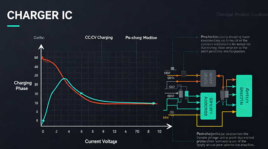
The common charging flow: CC → CV → stop
Most lithium chemistries follow the CC→CV pattern:
- Pre-charge (trickle) if the cell voltage is very low (a small fraction of nominal current).
- CC phase at the selected current (for example 0.2C, 0.5C, 1C).
- CV phase — hold voltage; current tapers down.
- Termination when current falls below a small percentage of the rated charge (or when a safety timer runs out).
For Li-ion the cell top is typically 4.20 V, for LiFePO₄ around 3.60–3.65 V. Always check the cell maker’s datasheet — that’s the final word.
Quick reference — typical charge parameters
| Chemistry | Full-charge voltage (per cell) | Typical pre-charge threshold | Common termination (current) | Float? |
| Li-ion (NMC/NCA) | 4.20 V | Pre-charge until ≈2.5–3.0 V at ~C/10 | 3–5% of charge current | No |
| LiFePO₄ (LFP) | 3.60–3.65 V | Pre-charge until ≈2.5 V at ~C/10 | 3–5% | No |
| Lead-acid (for context) | 2.40 V/cell (max) | — | Termination by absorption/time | Yes (float allowed) |
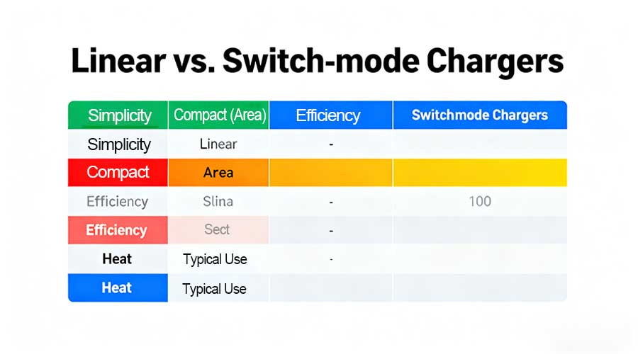
Linear vs. switch-mode chargers — pick the right tool
Short version: use a linear charger for low currents and simple single-cell USB designs; use switch-mode (buck/buck-boost) where efficiency, heat, or higher current matter.
| Aspect | Linear | Switch-mode |
| Simplicity | Very simple | More components |
| PCB area | Small | Larger |
| Efficiency | Low when Vin ≫ Vbat | High (often 85–95%) |
| Heat at higher current | Generates heat in chip | Much less heat |
| Typical use | <~500 mA USB chargers | Multi-cell packs, high current |
If you find yourself calculating watts of heat in the charger, that’s the cue to go switch-mode.
Heat matters — quick power table (linear chargers)
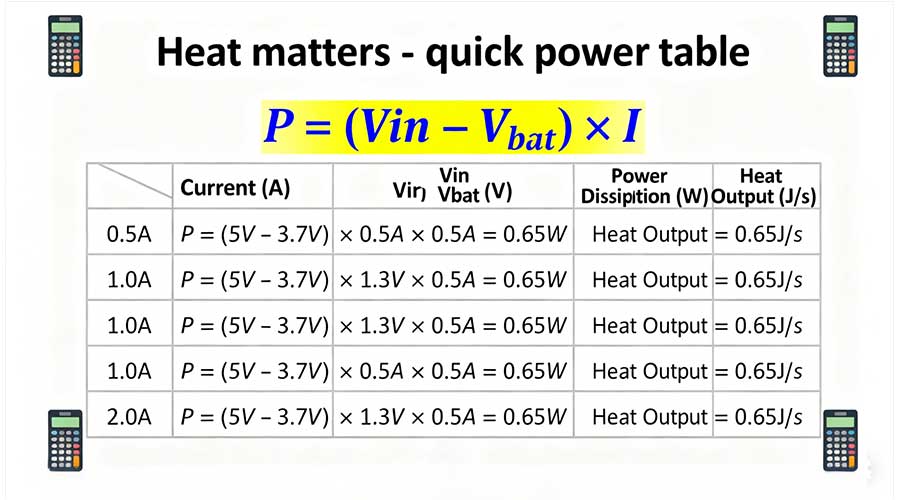
A linear charger turns the voltage difference into heat:
P = (Vin − Vbat) × I
Example for charging a single cell from 5.0 V USB (Vbat ≈ 4.2 V):
| Icharge | Voltage drop (V) | Power dissipated (W) |
| 0.5 A | 0.8 V | 0.40 W |
| 1.0 A | 0.8 V | 0.80 W |
| 2.0 A | 0.8 V | 1.60 W |
Even under 1 W can push small packages into thermal foldback. If you need >0.5–1 A continuous, seriously consider switch-mode.
Practical checklist — avoid common mistakes
· Match topology to current and input: >~500 mA or big Vin−Vbat → choose switch-mode.
· Plan thermal path: copper pours, thermal vias, and airflow matter. Don’t trust the chip datasheet alone.
· Include pack temperature sensing (NTC) — chargers should respect battery temp limits.
· Use correct sense resistor for accurate charge current and reliable termination.
· Protect against reverse connection and input transients (TVS diodes, soft-start).
· If series cells are used, make balancing part of the system — either in the charger or the BMS.
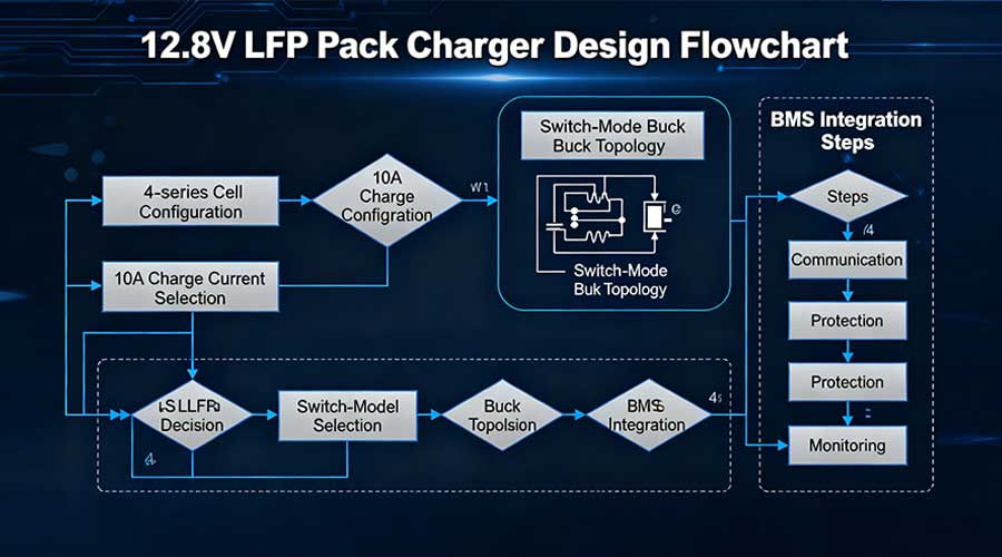
Example: sizing a charger for a 12.8V LFP pack
· Pack: 4 × LFP (nominal 12.8 V; full ≈ 14.6 V)
· Desired charge current: 10 A (≈0.25C for a 40 Ah pack)
· Recommendation: switch-mode buck charger (high efficiency) + BMS with balancing.
A linear solution would waste (Vin − 14.6 V) × 10 A in heat — which is impractical unless Vin is very close to pack voltage.
Closing — practical advice
Pick a charger IC that matches the chemistry and the expected operating current. For simple devices, a proven linear charger is fine; for multi-cell or high-power packs, design around an efficient switch-mode charger and a capable BMS. When in doubt: check the cell datasheet and size your thermal solution early in the design.
Need help?
If you’re specifying chargers or building custom packs, Himax Battery can help match charger topologies, pick ICs, and design pack-specific BMS and balancing solutions. Reach out to our technical team — we design for safety, performance, and manufacturability.