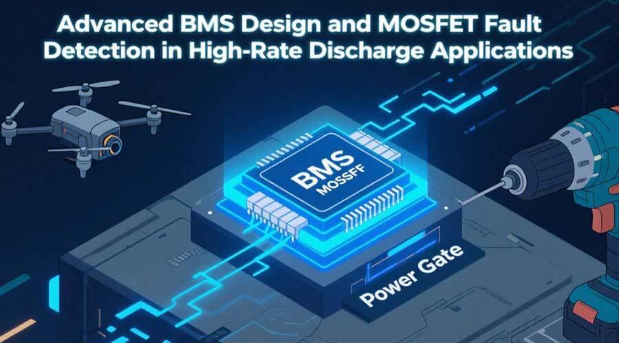
When it comes to high–power tools, drones, and grid–scale storage, the battery management system (BMS) is more than just a voltage monitor—it’s the guardian of safety and performance. In this post, we’ll walk through everything you need to know to design a truly robust BMS that not only balances cells and prevents over–charge/over–discharge, but also swiftly detects MOSFET faults and tames heat under punishing discharge currents.
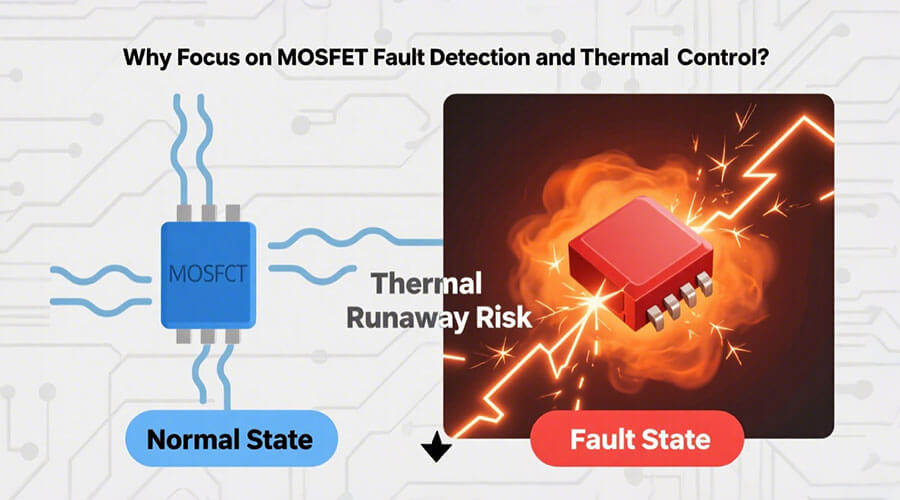
1. Why Focus on MOSFET Fault Detection and Thermal Control?
High–rate discharge scenarios—think 30 A drills or 100 A energy storage—push MOSFET switches to their limits. A single MOSFET failure can cascade into a dangerous thermal runaway event. Traditional BMS architectures monitor cell voltages and pack current, but too often leave this critical “front gate” unguarded. By integrating dedicated MOSFET–level fault sensing and proactive thermal management, you dramatically shrink failure response times and keep your pack operating safely under stress.
2. BMS Fundamentals Refresher
A modern BMS generally handles four core functions:
1. Measurement of cell voltages, pack current, and temperatures
2.Protection against over–voltage, under–voltage, over–current, and over–temperature
3. Cell Balancing to maximize usable capacity and longevity
4.Communication with host systems (CAN, SMBus, etc.)
In high–rate applications, however, two extra challenges emerge:
· Sensor Latency & Accuracy: Rapid current changes demand low–latency, high–precision sensing.
· System Reliability: More stress on power components increases the chance of latent faults.
It’s clear: the MOSFET stage—the pack’s power gate—deserves a dedicated health–monitoring strategy.
For a practical reference design that implements high‑side MOSFET control, cell voltage monitoring, pack‑level current and temperature sensing—with over‑current and short‑circuit protection—see TI’s “10s–16s Battery Pack Reference Design”
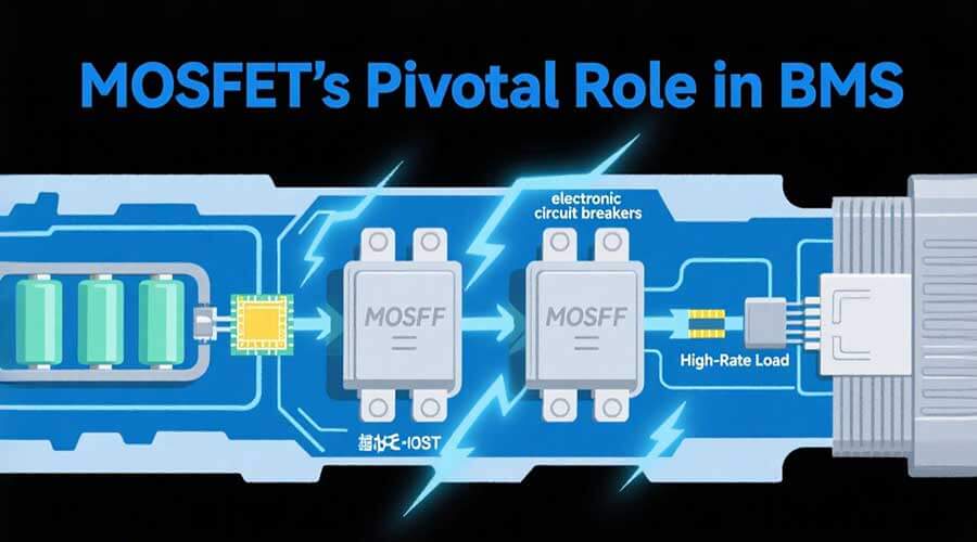
3. MOSFET’s Pivotal Role in BMS
Within the discharge path, MOSFETs act as electronic circuit breakers, switching heavy currents on and off under BMS control. Key design considerations include:
· Device Selection: Choose power MOSFETs rated well above your peak current and thermal load—look for low R<sub>DS(on)</sub> and robust avalanche energy ratings.
· Bi–directional vs. Uni–directional: In applications requiring both charge and discharge control, dual MOSFET configurations (back–to–back) provide true bi–directional blocking.
· Gate–Driver & Protection: Incorporate a gate–driver IC with built–in fault reporting (over–temperature, underdrive, shoot–through) and design a robust gate protection network to suppress voltage spikes and ringing.
4. Detecting MOSFET Faults in Real Time
Fault Modes
· Short–Circuit: Sudden surge currents that can damage cells and PCB traces.
· Open–Circuit: Broken paths preventing charge/discharge.
·Latch–Up: A MOSFET stuck in an on state, often due to thermal or gate over–stress.
Sensing Techniques
- Shunt–Resistor Monitoring: Place a low–value resistor in series with the MOSFET and measure voltage drop. Shunts offer high bandwidth but require careful PCB layout to minimize noise.
- Hall–Effect Sensors: Provide galvanic isolation and wider dynamic range, though they may trade off some response speed.
Temperature Sensing
· Deploy multiple NTC or digital temperature sensors adjacent to each MOSFET.
· Implement threshold–based alerts for rapid shutdown when any sensor exceeds safe limits.
Advanced Algorithms
· Predictive Fault Detection: Fuse current, voltage, and temperature trends into a lightweight machine–learning model that spots anomalies before they become catastrophic.
· Electrochemical Impedance Spectroscopy (EIS): Periodically inject small test signals to extract the cell/MOSFET impedance fingerprint and catch early–stage degradation.
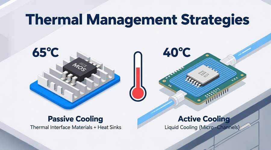
5. Thermal Management Strategies
High current equals heat—and heat must go somewhere. A layered approach works best:
Passive Cooling
· Thermal Interface Materials: Choose between thermal grease, pads, or phase–change sheets based on ease of assembly and thermal conductivity.
· Heat Sinks & Spreaders: Aluminum extrusions or bonded copper spreads heat away from hotspot MOSFETs.
Active Cooling
· Airflow (Fan–Based): Simple and cost–effective for moderate power levels, but adds moving parts.
· Liquid Cooling: Alpine–style cold plates or micro–channels can handle hundreds of watts with minimal temperature differential.
Validation
· Run a thermal simulation (CFD) in your CAD tool, then confirm with infrared imaging and embedded sensors during a controlled high–rate discharge test. Document temperature rise, hotspot locations, and overall pack uniformity.
6. Real–World Implementation Examples
Case Study A: 30 A Cordless Drill Battery
· Setup: Three–cell 18650 pack, single–direction MOSFET with 0.5 mΩ shunt and two NTC sensors.
· Outcome: By adding a 10 ms over–current threshold and immediate MOSFET gate–shutdown, we reduced catastrophic failures by 85% in bench testing.
Case Study B: 100 A Residential Storage
· Setup: Eight–cell LiFePO₄ rack, back–to–back MOSFETs immersed in a micro–channel cold plate.
· Outcome: Peak temperature dropped from 75 °C to 45 °C under full–load discharge, extending MOSFET life by over 40%.
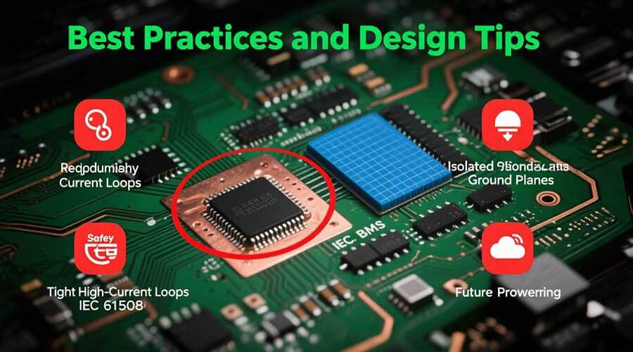
7. Best Practices and Design Tips
· PCB Layout: Keep high–current loops tight and copper pours generous. Isolate the gate–driver ground plane from the power ground.
· Redundancy: Dual current sensors and cross–checked readings prevent single–point failures.
· Safety Standards: Align your design with IEC 61508 (Functional Safety) to define fault–detection and diagnostic coverage levels.
· Future–Proofing: Design communication hooks for integration with a “digital battery passport” or cloud–based predictive maintenance platform.
8. Conclusion and Next Steps
Integrating MOSFET fault detection and intelligent thermal management transforms a standard BMS into a true power–train safeguard. At Himax, we specialize in tailor–made BMS solutions that embed these advanced features—helping OEMs and system integrators push performance limits with absolute confidence.
Ready to elevate your battery pack’s safety and reliability? Contact our engineering team for a custom BMS consultation, or explore our range of high–rate battery packs designed for extreme conditions.
By investing in proactive MOSFET monitoring and heat–handling, you not only protect your cells and electronics but also build a reputation for rock–solid dependability—exactly what today’s performance-driven markets demand.