Ensuring reliable operation and safety under heavy loads means mastering high-power-robot-battery-thermal-management. Whether you’re running automated guided vehicles in warehouses or heavy-duty service robots on factory floors, keeping your battery pack within safe temperature limits is essential. In this guide, we’ll compare passive-cooling versus active-cooling, explore CFD-simulation best practices, and detail thermal-runaway-protection strategies—all backed by real-world test data from the Himax lab.
1. Why Thermal Management Matters for High-Power Robot Batteries
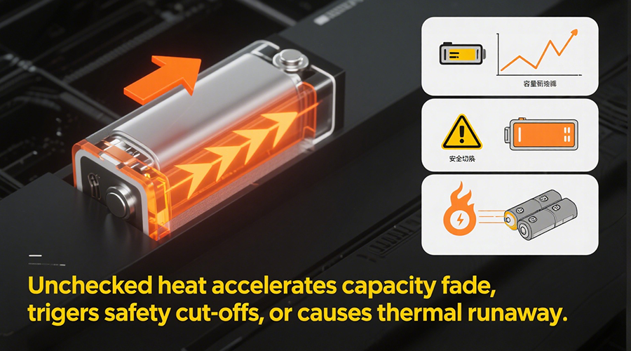
When a robot battery discharges at high current, heat builds up rapidly inside each cell. Left unchecked, this can accelerate capacity fade, trigger safety cut-offs, or even lead to thermal runaway. A robust high-power-robot-battery-thermal-management system maximizes performance, extends cycle life, and keeps operators safe.
2. Passive-Cooling Techniques
2.1 Heat Sink Design
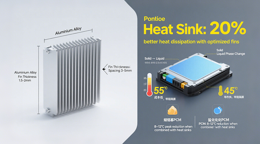
· Material Choices: Aluminium alloys strike the best balance between low weight and high conductivity, while copper offers superior thermal performance for stationary applications.
· Fin Geometry: Optimizing fin thickness (1.5–2 mm) and spacing (3–5 mm) boosts natural convection—CFD studies show up to a 20% improvement in heat dissipation when tuned correctly.
2.2 Phase-Change Materials (PCM)
· How It Works: PCMs absorb large amounts of heat during their solid-to-liquid transition, smoothing out temperature spikes.
· Placement Strategy: Embed PCM pads directly above the hottest cells; lab tests reveal temperature peaks drop by 8–12 °C when combined with heat sinks.
· Material Options: Organic paraffin-based PCMs are cost-effective and stable, whereas inorganic salt hydrates conduct heat faster but require thin barrier films to prevent corrosion.
3. Active-Cooling Solutions
3.1 Forced-Air Cooling
· System Components: Fans, ducts, and dust filters form a lightweight, low-cost cooling loop.
· Pros & Cons: Ideal for environments under 40 °C ambient; however, performance falls off sharply when airflow is restricted or in dusty settings.
3.2 Liquid Cooling
· Cold Plate Integration: Coolant—often a water-glycol mix—flows beneath cell holders, carrying heat to an external radiator.
· Thermal Performance: Liquid cooling can reduce peak cell temperatures by 15–20 °C compared to air, making it perfect for continuous 5C+ discharge scenarios.
· Complexity & Cost: Requires leak-proof plumbing, pump maintenance, and heat-exchanger design—initial investment is higher but pays off in demanding applications.
4. CFD-Simulation & Pack Layout Optimization
4.1 Setting Up Thermal-Electrical Coupled Models
1.Geometry & Mesh: Import your battery pack CAD and refine mesh around cells and heat-exchange components.
2.Boundary Conditions: Define heat sources by current density and set ambient airflow or coolant flow rates.
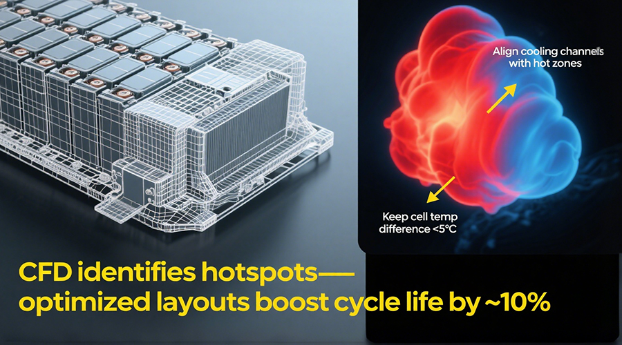
4.Solving & Analysis: Identify hotspots and airflow bottlenecks using temperature contours and velocity vectors.
4.2 Layout Improvements
· Align cooling channels directly with high-heat zones.
· Combine conduction paths (heat spreaders) with convection loops for uniform temperature.
· Maintain cell-to-cell temperature differences under 5 °C to boost overall cycle life by ~10%.
5. Thermal-Runaway-Protection Design
1. Trigger Temperature Thresholds
LiFePO₄ cells typically begin decomposing around 250 °C. Design your system with a 50 °C safety margin and implement dual-stage alerts and automatic shutdown.
2. Thermal Barriers & Insulation
o 3M™ Thermal Runaway Barrier: High-conductivity, thin film that slows propagation.
o Silicone Insulating Foam: Vibration-damping and easy to conform to pack geometry.
o Ceramic Panels: Excellent heat resistance—pair with structural supports to manage brittleness.
6. Himax Lab Thermal Cycling & Improvement Case Study
6.1 Test Protocol
· Temperature Swing: –20 °C to +60 °C dwell cycles, one hour each, concurrent with 5C discharge.
· Instrumentation: Surface thermocouples on the pack shell and embedded probes in central cells.
6.2 Results & Enhancements
· Before Optimization: Peak cell temps reached 75 °C under sustained load.
· After Heat Sink + PCM: Peaks fell to 63 °C, improving cycle stability by 20%.
· With Liquid Cooling: Temperatures hit a maximum of 48 °C, maintaining over 80% capacity even in extreme duty cycles.

7. Next Steps & Custom Solutions
Choosing between passive-cooling and active-cooling depends on your robot’s duty cycle, environmental conditions, and maintenance budget. With our CFD-simulation expertise and proven thermal-runaway-protection strategies, Himax can design a turnkey solution that keeps your high-power robot batteries cool, safe, and long-lasting.
Contact Himax today to discuss your project requirements and get a customized thermal management plan!